Commercial Vehicle Information Specifications
Overview
The ambition of the CVIS project is to develop a framework that can be used to define signal trees for different vehicle types, and then to use this framework to develop signal trees for vehicle types as e. g. Trucks, Trailers, Buses, and Passenger cars. The trees for these vehicle types shall share as much as possible of signals that can be commonly defined. The basis for common signals shall be the VSS tree. This tree has a focus on signals for passenger cars, but a significant part of these can very well be shared with the other vehicle types.
The CVIS project uses the Resource profile of the Hierarchical Information Model [HIM), which is fully compatible with the VSS rule set.
Trees for many vehicle types, such as passenger cars, trucks, vans, pickups, etc. can be based on the same “base tree” and for this the VSS vspec tree is used.
To enable the different modifications that are needed to “reshape” the VSS-tree from its passenger car centric structure to a tree that represents other vehicle types a tool is developed.
This tool i now on its third generation, the two first generations can be found on the himConfigurator branch of this repo.
The current version of the tool is named the vspecPreprocessor. It supports the same features for tree modifications as the previous generation but now without requiring usage of the extended vspec format (vspec2). It is written in python, the himConfigurator was written in golang which often required separate installation of the build system.
The basis of the framework that can be used to define signal trees for different vehicle types is the HIM configurator. It works as a pre-processor that reads the extended vspec format, vspec2, and processes the extended instruction set described below from which it generates vspec formatted files which are applied as input to the VSS-tools exporters to generate fully configured trees for desired vehicle types and models.
The HIM configuration instructions are declared in JSON formatted files. These instructions can be applied to trees that have a pre-configured vehicle type specific structure, or that have a vehicle type agnostic structure. The VSS-core tree is an example of the latter, while the other trees in the Vehicle directory have a pre-configure vehicle type specific structure.
A tree, whether it is vehicle type specific or not, shall be located on the spec/trees directory structure. These trees may then link to common objects which shall be located on the spec/objects directory structure. Vehicle specific trees can be derived from vehicle agnostic trees like the VSS-core tree without using the symlink mechanism.
The vision for this project is that vehicle specific trees will eventually be developed in separate Github projects that then will include the HIM configurator tool and a common vehicle agnostic tree as Github submodules or via other mechanisms, ths creating separate independent vehicle specific projects that are derived from a common signal source tree.
HIM configurator
The framework also contains a new tool, the HIM configurator. This tool is pre-processes vspec2 files to generate vspec files that are then used as input to the VSS-tools exporters. In its current version it provides support for the types of tree configuration that is described in the HIM extensions chapter below.
HIM extensions
The HIM syntax is in this project extended with the features described below. These can be preprocessed by the HIM configurator which transforms them into a HIM compliant format, thus making it possible to use the VSS-tools for exporting to other formats, including using overlays. When these extensions are used the file extension shall be “vspec2” instead of “vspec”. The rules for when the file extension “vspec2” shall be used instead of “vspec” are the following:
- A file that contains any extended syntax must be named with the file extension “vspec2”
- If a vspec2 file is referenced from within another file then this reference shall use the extension vspec if this file is located in the “trees” directory strucure.
- If a vspec2 file is referenced from within another file then this reference shall use the extension vspec2 if this file is located in the “objects” directory strucure.
Extension 1: Instantiation configuration
The HIM rule set supports the instantiation syntax inherited from VSS instantiation that can be used to request the VSS-tools to generate multiple instances of a branch/set of signals. This syntax has two options exemplified below
- instances: [“DriverSide”, “PassengerSide”]
- instances: Row[1,2] The examples above can be extended to two dimensions by using the array syntax, e.g.
instances:
    - Row[1,2]
    - ["DriverSide", "PassengerSide"]
which will generate a structure with four branches - Row1:DriverSide, Row1:PassengerSide, Row2:DriverSide, Row2:PassengerSide. It is however not possible to use this syntax to express a configuration where for Row1 there are two child nodes, e.g. [“DriverSide”, “PassengerSide”], and for Row2 there are three child nodes, e. g. [“DriverSide”, “Middle”, “PassengerSide”].
This missing flexibility is however provided in the extended syntax supported by the HIM configurator. A two-dimensional instantiation is then expressed in the vspec file as:
instances0: x #instanceTag
instances1: x #instanceTag
where ‘instances0’ is used for the ‘first-order’ instantiation (Row[1,2] in the example above), and ‘instances1’ is used for the ‘second-order’ instantiation ([“DriverSide”, “PassengerSide”] in the example above).
‘x’ is a placeholder for the instance expression in the file himConfiguration.json that is the input to the HM configurator, and ‘instanceTag’ is a unique name logically linking the two expressions, which must be preceded by a hash character (#). The two instance expressions can, but must not be on two subsequent rows. If not, then the second expression must be defined in any of the nodes that is part of the subtree under the node containing the first expression. The instance configuration input to the HIM configurator has a syntax as exemplified below.
    "instances": {
        "Seat": [
            "Row[1,2]",
            [
                [
                    "DriverSide",
                    "PassengerSide"
                ],
                [
                    "DriverSide",
                    "Middle",
                    "PassengerSide"
                ]
            ]
        ]
        }
The ‘Seat’ shown above is the instanceTag name that the HIM configurator will try to match in the vspec file.
The ‘first-order’ instantiation, in this case “Row[1,2]”, is followed by two ‘second-order’ instantiation expressions.
The number of ‘second-order’ expressions must match the number of instantiaions that the ‘first-order’ expression will expand to.
The expressions can use any of the two syntax options mentioned above.
Currently this syntax can only be used for two-dimensional instantiations.
Extension 2: Variability configuration
The tree in vspec format may contain multiple variations of objects that in a deployment typically are not included. An example are the Combustion engine and the Electric engine. in an ICE vehicle the former should be included, but not the latter. For an EV vehicle it is vice versa. To enable one or the other of these objects to be included the following syntax is used, example taken from the Engine.vspec.
VariationPoint: #EngineType
  - ICE #include CombustionEngine.yaml Engine
  - EV  #include ElectricEngine.vspec Engine
The keyword is VariationPoint, which on the same line must be followed by a hash sign (#) directly followe by a unique variation point tag (in this case EngineType. The value part of this key-value expression is an array of ‘variability object expressions’, where such an expression contains a ‘variability name’ followed by an ‘#include expression’. This expression must be compliant with the syntax rules for HIM #include expressions. The array size is not restricted.
The input to the HIM configurator for it to resolve which variations to select is found in two files.
- The Variability.json file,
- and the himConfiguration.json file.
The Variability.json file defines the available variations, and which include statements that should be selected for the variation. As can be seen in th PHEV variation example below it is possible to select multiple include statements.
    "EngineType": [
        {
            "PHEV": [
                "ICE",
                "EV"
            ]
        }
The himConfiguration.json file contains the variation that that should be included in the tree that is generated by the himConfigurator (using a VSS-tools exporter), expressed by the rows below in this example:
    "variants": {
        "EngineType": "PHEV"
Extension 3: Local variation point
If an instantiation configuration has a need of including a variation point with different variants for the different intances then the Variation point feature described above cannot be used as it would apply the same variant to all instances. To meet this need the Local Variation point (LocalVP) is available. An expression like shown below is inserted in the subtree to be instantiated
LocalVP: #AxleFeature
  - LIFTABLE #include Liftable.vspec Axle
  - STEERABLE  #include Steerable.vspec Axle
  - DRIVING  #include Driving.vspec Axle
The himConfiguration.json file is then updated with the different configurations for the different instances as shown below.
    "variants": {
        "AxleFeature.Row1": "AXLE+STEER",
        "AxleFeature.Row2": "AXLE+LIFT",
        "AxleFeature.Row3": "AXLE+STEER+DRIVE"
    }
As seen the AxlePoint local varation point name is extended with the names of the different instances Row1..Row3, which must be the same as the instantiation is configured with. The Variability.json shall then contain the definition of which include alternatives in the LocalVP command that shall be included.
    "AxleFeature": [
        {
            "AXLE": ""
        },
        {
            "AXLE+LIFT": "LIFTABLE"
        },
        {
            "AXLE+STEER": "STEERABLE"
        },
        {
            "AXLE+DRIVE": "DRIVING"
        },
        {
            "AXLE+LIFT+STEER": [
                "LIFTABLE",
                "STEERABLE"
            ]
        },
        {
            "AXLE+LIFT+DRIVE": [
                "LIFTABLE",
                "STEERABLE"
            ]
        },
        {
            "AXLE+STEER+DRIVE": [
                "STEERABLE",
                "DRIVING"
            ]
        },
        {
            "AXLE+LIFT+STEER+DRIVE": [
                "LIFTABLE",
                "STEERABLE",
                "DRIVING"
            ]
        }
    ]
With the above in place the HIM configurator will create the different variants for the different instances.
Extension 4: Allowed datatype reference
One of the information rule sets that HIM supports is the type definition rule set. A type definition tree is able to define structs and enums (allowed) that can be referenced from trees of other information types. Such a tree is defined in the spec/objects/Datatypes directory, currently containing the enums (allowed) that is used in the VSS tree. This tree has a structure that mirrors the structure from the VSS tree where the enums were originally used. This structure might later be changed to a more generic structuring to yield reference path names more decoupled from the VSS structure.
An external datatype reference to an enum (allowed) shall have a syntax as shown below.
datatype: Types.x.y.zValues
where x, y, z may be names providing an understanding of the defined enum (allowed) that conform to the node HIM node name syntax. The name z must be postfixed with the tag Values.
If the HIM configurator is used to substitute external enum (Allowed) references it will create a Datatype.yaml file in the root directory of the signal tree that it is working on. The node type in a type definition tree shall be ‘property’ but due to that the VSS-tools will reject separate trees with that node type, the node type ‘sensor’ is used instead. This must therefore be manually edited to rename to ‘property’ until a moodified version of VSS-tools is created, or that the HIM configurator is updated to handle the node type renaming.
Overlays
The HIM configurator supports invoking of overlays, which is then processed by the VSS-tools exporter. As it is fed to the VSS-tools overlay mechanism the syntax is identical. The path to the overlay files shall be added to the HIM configuration file as shown in the example below.
    "overlays": [
        "overlay/Truck/overlay1.vspec",
        "overlay/Truck/overlay2.vspec"
    ]
It is possible to disable the overlays by adding the CLI parameter -d, see Using the HIM Configurator. The file(s) generated by the VSS-tools exporter are saved in the spec/trees/exporterData directory.
Overlays on instantiations
The functionality provided by the Local Variation point extension, to be able to apply different configurations to the different instantiations, can also be realized using the overlays mechanism, but it requires some HIM configurator preprocessing. In the JSON input file to the HIM configurator the desired configurations are added associated with the “instance-overlays” key as shown in the example below.
    "instance-overlays": {
        "Vehicle.Chassis.Axle.Row1": "overlays/Truck/Steerable.vspec",
        "Vehicle.Chassis.Axle.Row2": "overlays/Truck/Liftable.vspec",
        "Vehicle.Chassis.Axle.Row3": "overlays/Truck/Steerable.vspec+overlays/Truck/Driving.vspec"
    }
The key of an added key-value pair is the path to the branch node under which the configuration shoul be inserted, and the value is the path to the desired overlay file. If more than one overlaysfile is to be applied to the same path then they are separated by a plus sign (+) as shown for the Row3 in the example. The node names in this overlay file shall be “relative”, i. e. they shall not be complete path expressions, the HIM configurator will handle this by prepending them with the key value before applying it as input to the overlays mechanism in the VSS-tools. An example of a relaive overlays file is shown below.
Driving:
  type: branch
  description: Axle driving features

Driving.IsDiffLocked:
  datatype: boolean
  type: sensor
  description: True if differential is locked on the axle.
These overlays files must be stored in the directories that is declared in the instance-overlays data. From the combined input mentioned above the HIM configurator will create temporary overlays files that are included in the call to the VSS-tools overlays mechanism. These files are automatically deleted after being used unless the -s or -p CLI parameter is used in the HIM configurator command.
Overlays creator
To support a scenario where a tree is to be built “from scratch” a tool named overlaysCreator has been developed. The assumption for the development of this tool was that at least parts of the tree will reuse existing and established structures. The tool will therefore take as input an existing tree in YAML format from which it will “pick” single leaf nodes, or subtrees, and write that into an overlays file. This overlays file can then be applied to any other tree, including an “empty tree” (a vspec file without any predefined nodes). An example scenario could be that a tree for a trailer should be built. The trailer tree should inherit the axle/wheel subtree structure from the VSS-core tree.
The first step would then be to create a him configuration file, e. g. named himConfig-trailer-base.json, that can configure the VSS-core tree with the desired axle/wheel layout, e. g. as shown below.
{
    "variants": {
        "AxleFeature.Row1": "AXLE+LIFT",
        "AxleFeature.Row2": "AXLE"
    },
    "instances": {
        "Axle": [
            "Row[1,2]",
            [
                [
                    "Pos6",
                    "Pos7",
                    "Pos9",
                    "Pos10"
                ],
                [
                    "Pos6",
                    "Pos7",
                    "Pos9",
                    "Pos10"
                ]
            ]
        ]
    }
}
This would then be used to create a YAML tree from the VSS-core.
$ ./himConfigurator -r Vehicle/VSS-core/ -c himConfig-trailer-base.json
Next the input file with instructions on which subtrees that should be picked from the created YAML tree is created, e. g. named himPickPaths.json and stored in the Vehicle/Empty directory.
[
    "Vehicle.VersionVSS",
    "Vehicle.Chassis.Axle"
]
With this pick file and the created YAML file as input, the overlays creator tool is called from the overlayscreator directory. The trailer tree is given the root node name Trailer by the -n Trailer CLI parameter. The go build command can be skipped if it is already built.
$ cd overlayscreator
$ go build
$ ./overlaysCreator -r Vehicle/Empty/ -y ../exporterData/cvis.yaml -p himPickPaths.json -n Trailer -o overlay/overlayPick.vspec
$ cd..
The final step is then to use the HIM configurator tool to build the trailer YAML tree from the Empty tree using the created overlays file. A HIM configuration file that instructs the tool to use it, e. g. named himConfig-trailer.json is created in the Vehicle/Empty directory.
{
    "overlays": [
        "overlay/overlayPick.vspec"
    ]
}
The HIM configurator is then used with the empty tree and the overlays file as input.
$ ./himConfigurator -r Vehicle/Empty/ -c himConfig-trailer.json
The YAML formatted trailer tree is now found as exporterData/cvis.yaml.
To populate the tree with more signals, create overlay files containing the wanted signal node data and then and add the paths to these overlay files to the overlay array in the himConfig-trailer.json file.
Tree development
The HIM rule set for resource data is used to define signals in a tree. This syntax can be directly used as input to any of the exporter tools provided by VSS-tools.
Trees under development
Currently the following trees are under development:
The VSS-core tree is a vehicle type agnostic tree that is configured by the HIM configurator to become vehicle type specific. Configuration templates for the vehicle types Car and Truck are available, and can be used as starting poin to create templates for other vehicle types. This tree uses the variation point and local variation point extensions to realize vehicle specific trees.
The VSS-core2 tree is also a vehicle type agnostic tree that is configured by the HIM configurator to become vehicle type specific. However, the usage of the variation point and local variation point extensions is here replaced by usage of overlays. This alternative leads to less modifications of the VSS tree to create the VSS core tree.
The other trees are vehicle type specific from the start, or for Driver a supplementary tree to be used together with e. g. the Truck tree.
Symbolic linking
The directory structure for a single tree follows the VSS pattern with “#include” links in the vspec files that logically links to other files of the tree. However, to link to a file in the common objects structure the corresponding file in the trees structure is realized as a symbolic link file. This means that when the content of the file is accessed the underlying file system follows the symbolic link to the file in the objects structure for the actual content of the file. This is transparent to the entity accessing the file, so e. g. the exporter tools from VSS-tools will when used for a transformation of a specific tree access file content from the common objects files transparently.
The symbolic links used in a tree structure definition shall be declared in a script file that can be run to refresh the symlinks if a link is broken. The syntax of these script files differ between Linux and Windows, see the chapter below.
Linux / Windows specific parts
Symlink script files
The symlink cript files used in Linux are standard bash script files, see e. g. cv-truck-symlinks.sh.
For Windows a Powershell script is used, see e. g. cv-truck-symlink.ps1 script in the Win-setup directory.
VSS-tools activation
The HIM configurator activates the VSS-tools exporter via a shell script. In Linux this is a Bash script, in Windows it is ealized by a Powershell script.
Information on how to install VSS-tools in Windows is found in the Win-setup directory.
Alignment with other standards
The terminology used in these HIM based specifications should try to align with terminology and principles from other standards. The cases that has been identified are described below.
Axle and tire locations
The ISO xxxx(number and link missing) specification includes a centerline based approach for commercial vehicles, see diagram below.
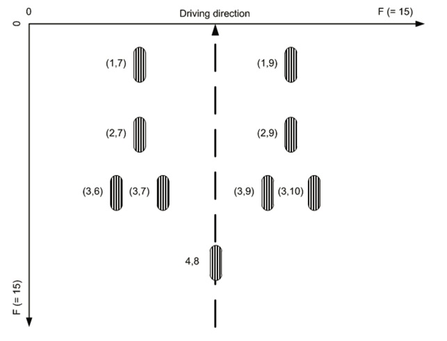
The ISO naming conventions shown in the figure above can be realized by providing the configuration shown below as input to the HIM configurator, and inserting the “instances0/1” directives in the related vspec files.
    "instances": {
        "Axle": [
            "Row[1,4]",
            [
                ["Pos7","Pos9"],
                ["Pos7","Pos9"],
                ["Pos6","Pos7", "Pos9","Pos10"],
                ["Pos8"]
            ]
        ]
    }
Further references, e.g. TMC VMRS, Fleet location codes, etc…