VISSR Feeders
A feeder is a Sw component that implements the following tasks, depending on which template version they implement:
The soon to be deprecated template version 1:
- Use an interface to the data storage for writing and reading data.
- Use an interface to the underlying vehicle interface for reading and writing data.
- Translate data from the format used in the “VSS domain” to the format used in the “Vehicle domain”, and vice versa.
Template version 2:
- Use an interface to the data storage for writing data.
- Use an interface to the underlying vehicle interface for reading and writing data.
- Translate data from the format used in the “VSS domain” to the format used in the “Vehicle domain”, and vice versa.
- Use an Unix domain socket interface for receiving “client set data” from the server.
Template version 3:
- Use an interface to the data storage for writing data.
- Use an interface to the underlying vehicle interface for reading and writing data.
- Translate data from the format used in the “VSS domain” to the format used in the “Vehicle domain”, and vice versa.
- Use an Unix domain socket interface for receiving “client set data” from the server.
- Use the UDS interface to receive instructions from the server on which signals to begin/stop issuing events after writing to the data store.
- Use the UDS interface to issue events when instructed by he server to do so.
Template version 4:
- Register with the server and receive a UDS socket on which the feeder shall listen for requests and issue events.
Please also see the feeder README files for more information about the different feeders.
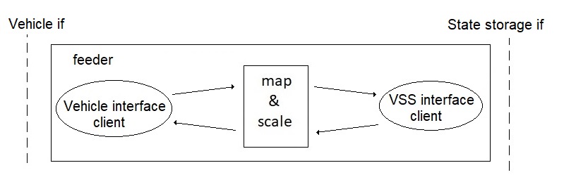
The SW architecture shown in figure 1 shows a logical partition into the three main tasks of template version 1.
The architecture shown handle all its communication with the server via the state storage.
This leads to a polling paradigm and thus a potential latency and performance weakness.
This architecture is therefore not found on the master branch, but available on the datastore-poll branch.
There is still a feeder design for this in the feeder-template/feederv1 directory.

- Figure 1. Feeder software architecture unoptimized polling
An improved architecture that eliminates the mentioned weaknesses for data flowing in the direction from the server to the feeder (i. e client write requests)
is shown in figure 2. For write requests the server communicates directly over an IPC channel with the feeder, thus removing the need for the feeder to poll
the state storage to find new write requests.

- Figure 2. Feeder software architecture optimized polling
A feeder implementing this solution can be found in the feeder-template/feederv2 directory. This feeder can be configured to either use an SQLite, or a Redis state storage interface, please see the Datastore chapter for details.
However, the solution implemented in the feederv2 template does not support that the server also can replace the polling with a more effective event based solution. For this the feeder implementation in the feeder-template/feederv3 directory needs to be used.
The server is able via the interface to detect whether a feeder implements version 2 or 3 of the interface. In case of version 2 it keeps poling of the data store, while for version 3 it relies on event signalling from the feeder instead. For more details of this interface, see the VISSR Server:Feeder interface chapter.
The feeder translation task is divided into a mapping of the signal name, and a possible scaling of the value. The instructions for how to do this is encoded into one or more configuration files that the feeder reads at startup. There are two versions of the feeder instructions, being used in template feederv1 and feederv2, respectively.
In version 1 this file only contains a signal name mapping, while version 2 supports also scaling instructions. For more about the telpate feeders, see the README in feeder-template directory.
An OEM wanting to deploy the VISSv2 tech stack needs to implement the Vehicle interface of the feeder, e. g. to implement a CAN bus interface. In the template feeders the Vehicle interface contains a minimal signal simulator that generates random values for the signals it is configured to support. All of that code should be removed and replaced by the code implementing the new interface client.
Besides the feeder templates there is also an rl-feeder where the Vehicle interface is implemented to connect to a RemotiveLabs broker. RemotiveLabs has a public cloud version of its broker that can be used to replay trip data available in VSS format.
There is also an External Vehicle Interface Client EVIC feeder that enables the interface client to be implemented in a separate executable.
Data storage interface
If the feeder is implemented to support multiple data base solutions, see the Data store chapter for which are currently supported, then to configure which to use could be done at startup via a CLI parameter, see e. g. how it is done in the feeder/feeder-template/feederv3/feederv3.go. There also the interface implementations to some DB solutions can be seen in the method statestorageSet(path, val, ts).
Feederv3
Feederv3 is the recommended feeder template to use as it is an evolution of the previous feeder templates and supports the latest feaure additions. More information on feederv3 is found in the Feederv3 chapter.